
Abstract: Spherical roller bearings are widely used in the main drive chain system of wind turbines due to their many application experience, low cost and convenient installation. They include floating and positioning bearings in the double-aligning bearing arrangement and a single self-aligning bearing arrangement. Positioning bearing in the form. However, with the continuous upgrade of the impeller diameter of wind turbines and the continuous increase of wind load in recent years, the application requirements for the main bearing are also getting higher and higher. Due to the relatively small contact angle of spherical roller bearings, under the action of a large axial load, the positioning end bearing is prone to single-row load-bearing phenomenon, and early wear is more likely to occur under poor lubrication conditions. In addition, the other row of rolling elements that do not participate in the load has a load waste during operation, and may also slip. The asymmetric spherical roller bearing proposed in this paper has been improved from the internal structure. Compared with the symmetrical spherical roller bearing, the bearing capacity is improved under the same size condition and the load wasted. Moreover, in order to facilitate the application of the wind power aftermarket, the internal structure is optimized while ensuring the interchangeability of external dimensions, ensuring that the bearings can be directly replaced without changing the dimensions of the main shaft and the bearing seat.
Keywords: spherical roller bearing; locating end bearing; early wear; asymmetrical spherical roller bearing; wind power aftermarket
0 Preface
As a key component of a wind turbine, the main drive chain system plays a vital role in the process of transmitting and bearing wind loads. With the continuous progress of wind turbine development, different main drive chain arrangements have been applied successively, and the corresponding main bearings are not the same. The reliability of the main bearings is directly related to the stability of the entire drive chain and even the entire wind turbine. Therefore, in the development process of the wind turbine, the selection of the main bearing is very important, and it needs to be confirmed in combination with the environmental conditions, load conditions, installation process and maintenance conditions of the wind turbine [1].
At present, the common wind turbines mainly focus on the horizontal axis arrangement, so the corresponding main drive chains are mostly cantilever beam structures. Under the action of wind load, the main bearing supporting the main drive chain has to bear a certain axial force in addition to the larger overturning moment. In addition, in order to compensate for the deflection and deformation of the main drive chain system during operation, the main bearing is required to have a certain centering function. Based on the above reasons, spherical roller bearings are widely used in the support structure of the main drive chain of wind turbines. The corresponding arrangement form is also more economical and applicable due to the low cost of spherical roller bearings, low precision requirements for peripheral parts, convenient installation and maintenance. So far, both onshore and offshore wind turbines have been applied, and the largest wind turbine used has reached 6.0MW. However, due to the limited axial load carrying capacity of spherical roller bearings, under the action of large axial load, only one row of rollers close to the gearbox is loaded, and the other row is in a no-load state, which will lead to load under conditions of insufficient lubrication. The contact surface of the row raceway wears early, and the other side slips. Literature [2-4] also proposed that the accuracy, clearance, viscosity and cleanliness of the lubricant at operating temperature of spherical roller bearings are very important for bearing applications. Therefore, it is necessary to study the relationship between load distribution and internal structure of spherical roller bearings, as well as the corresponding tribological characteristics. Professor Wang Jiugen of Zhejiang University once reviewed the tribological design of spherical roller bearings [5].
According to the special application conditions of wind turbines, this paper optimizes and analyzes the spherical roller bearings, and proposes a new asymmetric design. Under the same load conditions, the axial bearing capacity of the bearing is improved, and combined with the axial rigidity The stability of the shaft system was compared and analyzed. In addition, combined with the possible early wear of the bearing, the distribution of the p*v value of the internal wear factor of the bearing is simulated and calculated. And the feasibility of the optimized bearing was verified through experiments. Prevention and improvement measures are proposed for the common early wear failure mode of the spherical roller bearing at the positioning end of the wind power main shaft.
1 The arrangement of spherical roller bearings in the wind power main shaft
Among the currently installed wind turbines, more than half of the wind turbines use the main shaft bearing support structure, that is, the inner ring of the main bearing is installed on the rotating main shaft. According to the number of spindle support points, the arrangement of spindle bearings is divided into two-point support and three-point support. Spherical roller bearings are currently commonly used in the main shaft support application of doubly-fed wind turbines. This is because the transmission system of doubly-fed wind turbines generally includes hubs, main shafts, main bearings, gearboxes, generators, etc. The transmission chain is longer and needs to be considered The size expansion caused by the temperature rise of various components, and the impact of misalignment in the manufacturing and assembly processes on the system.
1.1 Two-point support layout
The two-point support using positioning end/floating end bearing support is the most typical arrangement, as shown in Figure 1. The bearings are installed in two independent or a common bearing housing. When the structure of the independent bearing seat is adopted, the main shaft has deflection deformation at the contact position of the inner ring of the bearing. In order to compensate for the misalignment of the main shaft and the bearing seat, a spherical roller bearing must be used. Because the main shaft has a certain amount of axial expansion due to the temperature difference, one bearing is required for floating compensation, and the other is a positioning bearing. In order to reduce the impact of the floating amount of the main shaft on the primary planet carrier of the gearbox, the positioning end bearing is placed on the gearbox side. Finally, the floating end bearing on the hub side bears the main radial force, and the positioning end bearing bears a certain radial force and axial force.
1.2 Three-point support layout
The positioning end bearing in the three-point support arrangement is generally placed outside the gear box, and the other two support points are the primary planet carrier support bearings in the gear box, as floating end bearings, as shown in Figure 2. The locating end bearing often uses an independent bearing seat, which needs to be able to compensate for the deflection and deformation of the floating end bearing of the first-stage planet carrier and bear the axial load in the wind load, and must use a spherical roller bearing. Another important point is to ensure the correct distance between the positioning end bearing position and the floating end bearing position during installation to ensure that the axial force acts on the positioning end bearing. With three-point support, the support bearings in the gearbox as two support points also need to withstand wind loads. It is necessary to consider the impact of other factors such as the vibration, thermal expansion, and axial movement of the main shaft on the gearbox.
.jpg)
2 Introduction of asymmetric spherical roller bearings
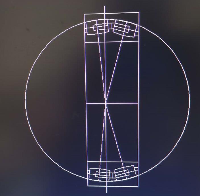
For the positioning end bearings of the above two arrangements, in addition to the radial force, they also need to bear a larger axial force during the application process. Since traditional spherical roller bearings are symmetrical, the contact angles of the two rows of raceways are the same. When the ratio of axial force to radial force is greater than e, the bearing load is mainly borne by one row, as shown in Figure 3. In this situation, if the bearing is poorly lubricated, early wear is likely to occur.
.jpg)
The asymmetric spherical roller bearing optimizes the contact angle of the raceway of the load-bearing row, so that the axial load-carrying capacity of the bearing is significantly improved. In addition, in order to ensure the stability of the bearing during operation, the dimensions of the rolling elements in the two rows are the same. In wind power application conditions, the large contact angle is placed on the side of the gearbox, and the small contact angle is placed on the side of the hub. The shape of the asymmetrical spherical roller bearing is the same as that of the traditional symmetrical spherical roller bearing, as shown in Figure 4. There is no need to change the design dimensions of the main shaft and the bearing seat while replacing the bearings, so asymmetrical spherical roller bearings can be used interchangeably with symmetrical spherical roller bearings, especially for the aftermarket of wind power, in the existing wind turbine upgrades and main bearings The replacement has good feasibility. In addition, there are many other advantages. This article will give a detailed introduction to asymmetric spherical roller bearings through a comparative analysis with ordinary bearings in combination with specific loads.
3 Analysis of the advantages of asymmetric spherical roller bearings
3.1 Analysis of bearing capacity
Taking the application of the locating end bearing in the three-point support arrangement as an example, the load capacity of the conventional symmetrical spherical roller bearing 240/800 and the asymmetrical spherical roller bearing 240/800 is compared and calculated. For the special working condition where the bearing at the locating end bears a large axial force, in order to make the comparison obvious, the working condition where the ratio of the axial force and the radial force is greater than e is selected. The calculation uses our internal dedicated bearing analysis software. The load results at the bearing under this condition are shown in Table 2.
.jpg)
Figure 5 is a comparison of two-row roller bearing curves of conventional symmetrical spherical roller bearings 240/800 and asymmetrical spherical roller bearings 240/800 calculated under assumed load conditions. From the figure, you can see the conventional symmetrical bearings. Under this load condition, a single-row load-bearing phenomenon occurs, and the asymmetric bearing avoids this phenomenon under this load, and the load of the main load-bearing row is also reduced, thereby improving the overall bearing capacity of the bearing. From Figure 6 we can find the contact stress curve of the rolling elements of the asymmetric spherical roller bearing 240/800. Because the rolling elements are specially shaped, the edge stress of the rollers is avoided.
.jpg)
In addition, under fatigue load, the contact stress of asymmetric spherical roller bearings is also significantly reduced. Figure 7 shows the fatigue contact stress statistics of three different internal structure spherical roller bearings. From the comparison results, it can be found that the overall contact stress level of the asymmetric spherical roller bearing is the lowest. With the development of low-wind speed wind farms in recent years, more large-blade wind turbines have been developed and applied, and the corresponding fatigue load has also increased significantly. As a result, many original models need to be increased in size to meet the fatigue load requirements. The use of asymmetrical spherical roller bearings can significantly improve this situation, and can be used for fans with larger blades without changing the outer dimensions of the main bearing. In addition, super-finishing the bearing raceway can also significantly improve the life of the bearing.
3.2 Axial rigidity analysis
In addition to the carrying capacity, the axial rigidity of asymmetric spherical roller bearings is also significantly improved. Due to the unstable wind conditions, the main drive chain system of wind turbines needs to overcome certain impacts while supporting and transmitting huge loads. Especially as the positioning end bearing, by bearing the axial impact load, it can alleviate the bearing condition of the first-stage planet carrier of the gearbox during operation. It also has a certain protective effect on the use of the gearbox. Figure 8 shows the corresponding axial displacements of the three types of bearings under different axial forces. It can be found that the overall axial displacement of the asymmetric spherical roller bearing is significantly smaller than that of the symmetrical spherical roller bearing.
3.3 Bearing dynamics analysis
According to the literature [3], the wear of the material is inversely proportional to the (p*v) factor, where p is the normal pressure of the contact pair and v is the relative sliding speed of the two contact pairs. FV used the bearing dynamics simulation analysis software CABA3D? to compare and analyze the p*v values of different bearings. From Figure 9 it can be found that only two points along the roller axis of the spherical roller bearing are pure rolling when loaded, where p*v is close to zero, and other areas have microscopic relative sliding. On the contrary, the p*v value of the asymmetric spherical roller bearing is in a stable state throughout the bearing range of the roller, and there is no abnormal peak. Combined with the current common failure modes of spherical roller bearings, the early spalling of the bearing rolling elements generally starts from both ends, which is consistent with the trend of p*v in the calculation results in Figure 9. The use of asymmetric spherical roller bearings can significantly improve the p*v value along the rollers during the operation of the bearing, thereby reducing the risk of early wear and failure of the bearing.
.jpg)
3.4 Practical application and test analysis
In order to verify the feasibility of asymmetric spherical roller bearings, FV conducted a comparative test analysis on different bearings through an internally developed test bench. Figure 10 shows the friction of different spherical roller bearings under larger axial load conditions. Moment. As the size of the bearing continues to increase, the advantage of asymmetrical spherical roller bearings with small friction torque becomes more and more obvious.
.jpg)
In addition to the above analysis, in order to facilitate the application, the interchangeability of bearings is guaranteed under the same external dimensions. Therefore, asymmetric spherical roller bearings have already been put into use in the post-wind power market. In combination with the current practical application of asymmetric bearings, Figure 11 shows the temperature distribution of the main bearing at different powers during a period of fan operation. It can be clearly seen that the average operating temperature of asymmetric spherical roller bearings is compared with that of symmetrical spherical roller bearings. The sub-bearing is at least 2 degrees lower, which from the application point of view proves the advantage of asymmetrical spherical roller bearing with lower overall friction.
4. Conclusion
This article compares and analyzes the application of different spherical roller bearings under different working conditions, and gives a detailed introduction to asymmetric spherical roller bearings. The specific features and corresponding advantages are summarized as follows:
Asymmetrical spherical roller bearings and traditional symmetrical spherical roller bearings are interchangeable in shape. By improving the internal structure, the bearing capacity of the bearing is improved, and the axial rigidity is also significantly improved. Ensure that the bearing can be used in both new projects and after-market upgrade fans.
The rolling element modification improves the contact stress of the bearing and reduces the p*v value of the bearing, thereby reducing the risk of early bearing wear.
In the process of machining, the super-precision process of the raceway is added, which improves the rated dynamic load of the bearing, thereby increasing the service life.
The improved tribological performance of the asymmetric spherical roller bearing is verified by the combination of experimental test and practical application. It has been verified that the actual average operating temperature of asymmetrical spherical roller bearings is at least 2 degrees lower than that of symmetrical spherical roller bearings.

.jpg)
.jpg)
.jpg)